

FM Radio Receiver Module DIY Electronic Kit 76-108MHz DIY Radio Speaker Kit Frequency Modification LCD Display Soldering Practice

 Direct purchase from the factory
保證安全結帳

 免費禮物
免費禮物
 運送政策
運送政策 退貨政策
退貨政策免費禮物
歡迎來到Roymall,您的專業購買高級百貨禮物的網站。我們非常重視並感謝您的支持,並希望通過為您的購買增添額外的驚喜來表達我們的感激之情。當您與我們一起購物時,您不僅可以享受提升生活品質的高品質產品,還可以在每次訂單中獲得獨家免費禮物。 準備好探索我們的收藏並找到您的完美禮物了嗎?瀏覽我們的高級百貨商品選擇,下訂單,並期待您的免費禮物與您的購買一起到來。運送政策
我們將努力在收到您的訂單後將商品安全送達您手中。運送詳情將在您的確認郵件中提供。在大多數情況下,訂單將在2天內處理。在特殊情況下,可能會延遲如下:當您在週六、週日或公共假期下訂單時,將延遲2天。通常需要5-7個工作日(週一至週五),不受航班延誤或其他環境因素影響。由於我們的運送服務是全球性的,運送時間將取決於您的位置,因此可能需要幾天時間,如果您位於偏遠地區或國家,請耐心等待。1. 退貨與換貨政策
我們僅接受在roymall.com購買的商品。如果您從我們的本地分銷商或其他零售商處購買,則無法在我們這裡退貨。 最終銷售商品或免費禮物不可退貨。要符合退貨條件,您的商品必須未使用且與收到時的狀態相同。還必須保留原始包裝。收到我們的退貨指示後,請將退貨商品打包並將包裹送至當地郵局或其他快遞服務。我們將在收到退貨商品後3-5個工作日內處理您的退貨或換貨。退款將自動處理並記入您的原始付款方式。如果商品是根據訂製生產的,包括訂製尺寸、訂製顏色或訂製印刷,則不可退貨或換貨。需要更多幫助,請聯繫我們。 service@roymall.com 或 Whatsapp: +8619359849471
2.退款政策
在我們收到並確認退貨包裹後,您將獲得全額退款或100%商店信用。退款將自動處理並記入您的原始付款方式。 請注意,運費及任何關稅或費用不可退款。包裹發貨後,額外運費不可退款。您需負責支付這些費用,我們無法免除或退款,即使訂單被退回給我們。一旦我們收到並確認您的退貨商品,我們將向您發送電子郵件,通知您我們已收到您的退貨商品。我們還將通知您退款的批准或拒絕。如果您在退款過程中有任何問題,請聯繫我們。 service@roymall.com 或 Whatsapp: +8619359849471Introduction:
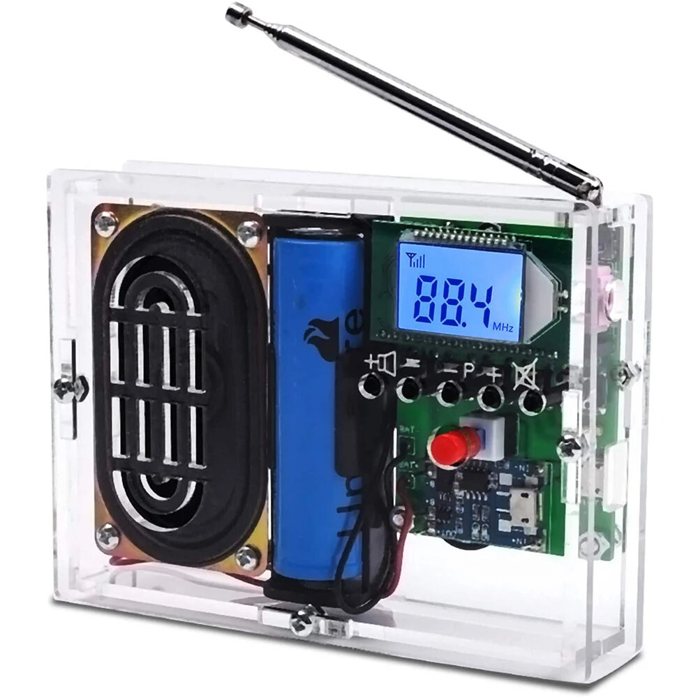
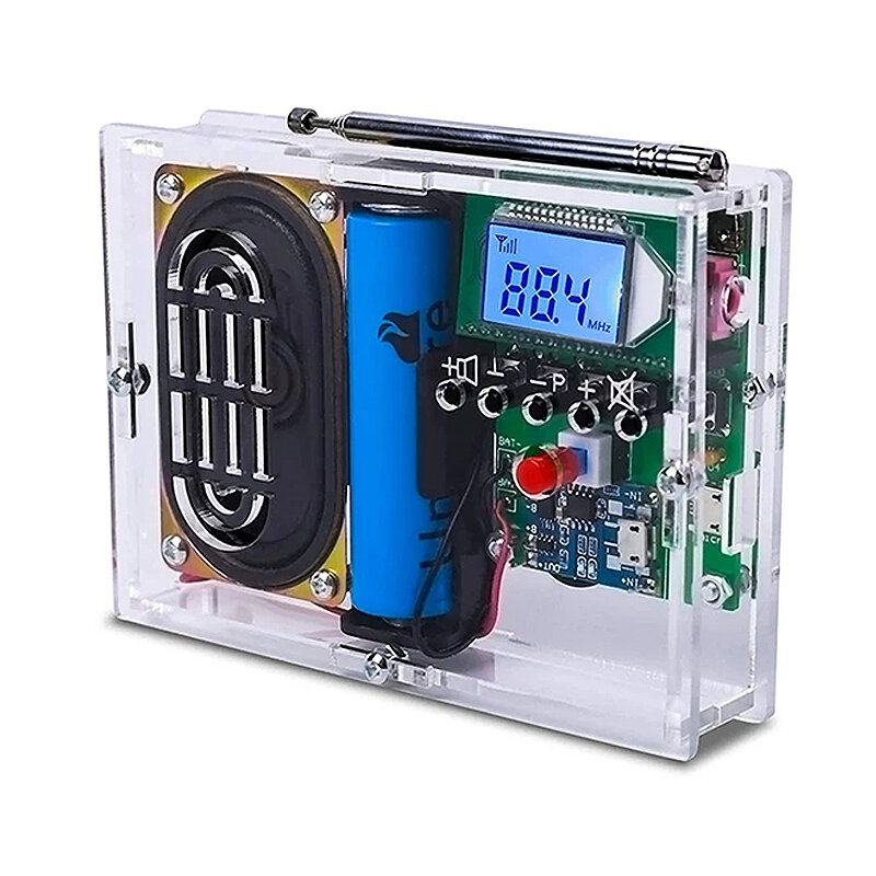
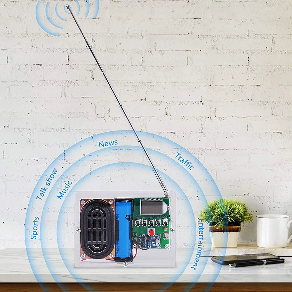
It is an 76.0MHz-108.0MHz Wireless FM Radio Receiver DIY Kit. It has a built-in high-definition display LCD display screen which can clearly display the receiving frequency and it can store 22 radio stations, which is enough to meet your needs.
Feature:
>>>Manual: Click here to open<<<
1. LCD Display FM Radio Receiver DIY Kit
2. Work Voltage: DC 3.0V~5.0V
3. Output impedance: 8ohm
4. Output power: 5W
5. Output channel: Mono for speaker and Dual channel for earphone
5. Frequency: 87.0MHz~108.0MHz (Disable CampussBroadcasting Band)
6. Frequency:76.0MHz~108.0MHz (Enable CampussBroadcasting Band)
7. Equivalent noise: >=30dB
8. Automatically search for radio stations
9. Built-in 30-level digital volume adjustment
10. Automatic memory function after power off
11. Built-in rechargeable module
12. Power saving mode with backlight off for 20 seconds
13. Support speaker and earphone audio output
Use Methods:
1. Keep press AUTO button to automatically search and store the radio stations that can be listened to.
2. Automatically name searchable stations like P01,P02,P02 and so on.
3. Press P+ and P- to switch saved stations.
4. Press V+ and V- to adjust volume from V00 to V30.
5. Switch CampusBroadcasting Band: Keep press V+ and V- before power ON and then turn ON work power switch. It means enable CampusBroadcasting Band if display C1 on LCD. It means disable CampusBroadcasting Band if display C0 on LCD.Available after restart.
6. Enable backlight mode: Keep press P+ and P- before power ON and then turn ON work power switch. It means keep backlight ON if display B1 on LCD. It means the backlight will turn OFF after 20second if display B0 on LCD(This is the power saving mode).Available after restart.
7. It can output audio from speaker and earphone jack. The speaker of the module does not work when the earphone is connected.
Note:
1. It cannot receive radio while it is charging.
2. It is a wireless module. So do not use it in an environment with siggnal interference.
3. Input charging voltage form micro USB on the bigger PCB.
Installation Tips:
1. User needs to prepare the welding tool at first.
2. Please be patient until the installation is complete.
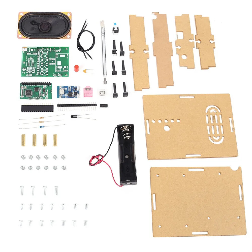
3. The package is DIY kit. It need finish install by user.
4. The soldering iron can"t touch the components for a long time(1.0 second), otherwise it will damage the components.
5. Pay attention to the positive and negative of the components.
6. Strictly prohibit short circuit.
7. User must install the LED according to the specified rules. Otherwise some LED will not light.
8. Install complex components preferentially.
9. Make sure all components are in right direction and right place.
10. It is strongly recommended to read the installation manual before starting installation!!!
11. Please wear anti-static gloves or anti-static wristbands when installing electronic components.
Installation Steps (Please be patient install!!!):
Step 1: Install 1pc 39Kohm Metal Film Resistor at R1.
Step 2: Install 2pcs 10Kohm Metal Film Resistor at R2,R3.
Step 3: Install 1pc SOP-16 IC LM4863 at U1.There is a mark on one end of the IC and there is a mark on PCB where the IC can place on.These two marks are corresponding to each other and are used to specify the installation direction of the IC Socket.
Step 4: Install 1pc micro USB socket at J2.
Step 5: Prepare 6pcs pin header.
Step 6: Install 1pc Charging Module at J7 and fix by 6pcs pin header.
Step 7: Remove black fixed block from 6pcs pin header and fix Charging Module.
Step 8: Install 1pc 0.1uF Monolithic Capacitor at C2.
Step 9: Install 1pc 1uF 50V Electrolytic Capacitor at C1.Pay attention to distinguish between positive and negative.The Longer pin is positive pole.
Step 10: Install 1pc 3.5mm Audio Socket at J5.
Step 11: Cut a pin from 16Pin Female Socket.
Step 12: Install Female Socket at FM.Pay attention to the direction of the cut pin.
Step 13: Install 1pc Self-locking Button at S6.
Step 14: Install 5pcs 6*6*20mm Black Button at S1-S5.
Step 15: Install 1pc Self-locking Button Cap on Self-locking Button.
Step 16: Install 1pc Antenna at ANT.Note that the antenna should be installed on the front of the PCB.
Step 17: Install 1pc 18650 Battery Box at J1,J3.Pay attention to the positive and negative.Red wire is positive pole.
Step 18: Install 2pcs 15cm black Cable on speaker.
Step 19: Connect speaker to PCB at SP. The speaker does not distinguish between positive and negative.
Step 20: Install 1pc FM Audio Receiver on Female pins.Pay attention to the direction of the cut pin.
Step 21: Tear off the protective film on the surface of the acrylic shell.
Step 22: Install 4pcs M3*15mm Copper Pillar and 4pcs M3*10mm Screw on Acrylic bottom plate.
Step 23: Fixed speaker on acrylic bottom plate by 4pcs M3*6mm Screw.
Step 24: Install 3pcs M3*6mm Screw and 3pcs M3 Nut on Acrylic bottom plate.Note that the wire should not be placed between the PCB and the acrylic.
Step 25: Fixed main PCB on acrylic bottom plate by 3pcs M3 Nut.Note that the wire should not be placed between the PCB and the acrylic.
Step 26: Adjust the position of the battery box. Do not place the wires under the battery box. The wires can be moved to both ends of the battery box.
Step 27: Fix other acrylic plate by 6pcs M3*6mm Screw and 6pcs M3 Nut.
Step 28: Connect to power supply and enjoy the effect.
| No. | Component Name | PCB Marker | Parameter | Quantity |
| 1 | LM4863 | R7 | SOP-14 | 1 |
| 2 | 3.5mm Audio Socket | R1,R2.R4,R5,R8~R14 | 5Pin | 1 |
| 3 | Monolithic Capacitor | R3 | 0.1UF 104 | 1 |
| 4 | Electrolytic Capacitor | Y1 | 1uF 50V | 1 |
| 5 | Metal Film Resistor | C1,C2 | 10K ohm | 2 |
| 6 | Metal Film Resistor | TEA5767 | 39K ohm | 1 |
| 7 | FM Audio Receiver | LM386 | 41*22mm | 1 |
| 8 | Black Button | U1 | 6*6*20mm | 5 |
| 9 | Micro USB Socket | R6 | SMD | 1 |
| 10 | Antenna | C4,C5,C6 | 80mm-255mm | 1 |
| 11 | Female Pin | C3,C9,C11 | 16Pin | 1 |
| 12 | Self-locking Button | C7,C8 | 8*8mm | 1 |
| 13 | Self-locking Button Cap | Q1-Q4 | Red | 1 |
| 14 | 18650 Battery Box | 5V | 1 | |
| 15 | Male Pin | D13 | 7Pin | 1 |
| 16 | Charging Module | 056SMC_4 | 26*18mm | 1 |
| 17 | Cable | S4 | 15cm | 2 |
| 18 | Speaker | S4 | 8ohm 5W | 1 |
| 19 | Acrylic Shell | S1,S2 | 6 | |
| 20 | Copper Pillar | LM386 | M3*15mm | 4 |
| 21 | Screw | U1 | M3*10mm | 4 |
| 22 | Screw | X1 | M3*6mm | 14 |
| 23 | Nut | M3 | 12 | |
| 24 | PCB | SP | 1 |
Package Include:
1x LM4863
1x 3.5mm Audio Socket
1x Monolithic Capacitor
1x Electrolytic Capacitor
2x Metal Film Resistor(10Ku03a9)
1x Metal Fim Resistor(39Ku03a9)
1x FM Audio Receiver
5x Black Buttons
1x Micro USB Socket
1x Antenna
1x Female Pin
1x Self-locking Button
1x Self-locking Button Cap
1x 18650 Battery Box
1x Male Pin
1x Charging Module
2x Cables
1x Speaker
6x Acrylic Shells
4x Copper Pillars
4x Screws(M3*10mm)
14x Screws(M3*6mm)
12x Nuts
1x PCB


